Transitioning to a Hybrid Security System
Like the security systems of many aging homes, my security system was exclusively wired. For cost savings, I had dropped our security company contract several years back, but had maintained the system for personal use. Though minimal, the system still worked and accomplished everything that I needed.
Prices in wireless home automation have declined recently and products are now available for the average homeowner to use. However, my old Honeywell Ademco Vista 10SE alarm control panel, installed circa 2000, only supported wired components. Thus began my odyssey into upgrading our security system.
At the end of the project when everything was working, I realized that the entire project would have been much easier with better documentation of the programming process. Hopefully, what follows will help the next intrepid installer to move more quickly and sure-footedly through the process.
Choosing the Hardware
I opted for a minimal, but expandable, installation as a base. This will allow for expansion as
new functions are needed. All components came through Amazon to my doorstep. I ordered the following:
- Honeywell Vista 20P control panel[1] with metal cabinet (“can”)[2]
- Honeywell 6760RF keypad
- 12V 7Amp alarm battery (the exact battery depends on your control panel and how long you want your system to function without power.)
- White B Connector wire splices for low voltage wires (such as Dolphin brand)
This is a basic installation. Once this is up and working, various communicators, more keypads (wired or wireless) and wireless components may be added.
Preparing to Install
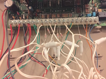
Before touching anything, get out your phone and snap pictures of the inside of the control panel and wiring. Shoot from many angles because one angle may be better than another for seeing a particular wire. Make sure that you can see any numbers printed below the circuit board contact points (the row of screws). In the picture here, the numbers can be seen along the slim green strip of circuit board below the contact points.
You will also need to gather the following tools for your physical installation:
- Phillips screwdriver
- Flathead screwdriver
- Wire stripper/cutter
- Wire crimper (or pliers used gently as a substitute)
- Pencil
- Masking tape or blue painters tape for temporary labeling of wires
- Sharpie for marking wire labels
You may also need:
- Drywall anchors or another sort of wall anchor
- Drill
- Hammer
- Labeler (such as Brother P Touch) with plastic labeling
- Zip ties
Labeling the Wires
Labeling your existing wiring is the most important step. Be sure to disconnect the power from your control panel before beginning.
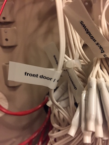
I found two types of labeling helpful. First, label the cables. You will see clusters of 2, 4 or 6 thin wires enclosed together within a plastic cover. This is a multi-strand wire, otherwise known as a cable.
Using masking tape for temporary labels, label each cable with:
- the current zone number
- a description and location of the component, such as upstairs siren, front door contact, or garage motion detector.
Finally, label each individual wire within a cable with the current control panel connection number.
Important: before you restore power at the end of your physical installation process, all masking tape labels must be removed. The individual wire labels should no longer be necessary, so may simply be removed and not replace. The cable labels should either be removed or replaced with permanent plastic labels (Brother P Touch or some other type of electrical wire label).
Installing the Hardware
The nice people at AlarmGrid did an excellent job of creating videos which go through the physical replacement of an old hardwired alarm panel with a new Vista 21iP. The same steps apply to installing a Vista 20P with two small exceptions. First, there will not be any lights on the Vista 20P when you power it up. Second, the Vista 30P will not have an ethernet port on the panel.
I recommend watching all the videos in sequence first before touching anything. Then, watch each video as you complete that step of the replacement process.
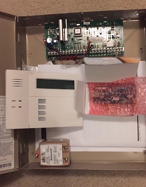
Reusing Your Existing Cabinet
The cabinet for my existing Vista 10SE was identical to the new cabinet which came with my Vista 20P. I was happy to reuse the existing cabinet and simply switched out the circuit board. A wiring diagram is attached to the inside of the cabinet door. If you reuse the old cabinet, remember to swap the old cabinet door for the new cabinet door so that you have the new wiring diagram. Do this by simply sliding the the door upwards to disengage the hinges and remove. Reverse the process to attach the new cabinet door.
Understanding the Role of Programming
So, you’ve installed the new hardware. Now, you need to tell the alarm system what components are connected (door contacts, windows contacts, motion detectors, heat detectors, etc.) You also need to tell the system how you want it to behave. Do you want the doors to chime when they are opened? What codes do you want for enabling/disabling the system? Do you want your alarm to beep to indicate that it is armed?
This is really where the documentation is very reference-oriented rather than “how-to.” There are so many options, but most can be ignored because the default value are fine. The basic programming required to get your system up and running is described below.
We will use a very typical two-story home example. There is a front door, back door and door from the house into the garage, which we will call the "garage door". These are all on the first floor of the house. There are various windows on the first floor and on the second floor. Additionally, there is a single motion detector on the first floor.
The zones for the example are wired as follows:
- Zone 1 is the front door.
- Zone 2 is the garage door.
- Zone 3 contains the windows on the front of the first floor of the house.
- Zone 4 contains the windows along the back and side of the first floor of the house.
- Zone 5 contains the windows on the second floor of the house.
- Zone 6 is the first floor motion detector.
Avoiding the Gotchas
- Each keypad has an “address”. The address is how the control panel knows with which keypad it is communicating. You can think of the “address” as a name for the keypad. The first keypad that you connect must be address 16. Nothing will work unless you give the first keypad address 16. You will see this done during the AlarmGrid videos.
- Programming can be done in one long sequence or in small batches. Each time you have finished a batch of programming, you must save your changes. Saving is done by entering either * 98 or * 99. Unless you have a good reason, always use * 99. If you enter * 98, you will not be able to re-enter the programming mode via the keypad. Basically, you are locked out unless you use what is called “the backdoor” method of entering programming. When your alarm is faithfully functioning as you like it, you might make the choice to do a final save using * 98, but think long and hard before doing this.
- If met with a single long beep when trying to enter programming mode, you are locked out. You probably exited programming the last time with * 98, as explained above. Time to find the “backdoor”., explained in the Glossary
- Each control panel has an installer code. The installer code is an access code with a particular set of authorities. The default installer code from the manufacturer is 4112. For security, reset this after all your programming is done. A stealthy thief could use it to disable features. Once this code has been reset, do not lose your new code! As with the thief, you will also not be able to accomplish certain things without this code. When you sell your house, provide the new installer code to the next owner.
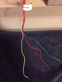
- Are you trying to program the system, but cannot enter programming mode? You are met with a beep for each of the first four buttons pressed, but then nothing else. This likely indicates a wiring issue. This happen to me. After much frustration and internet searching, I found that one of the data wires on the back of my keypad had broken from manipulation during the physical installation. The red and black power wires were both fine so the keypad powered up normally. However the broken wire was the green data wire which keeps the keypad and controller from communicating.
Documenting Zone Details
Before you begin programming, you need to write out certain details for each zone that you will program. There is an intricate worksheet included in the back of the Vista 20P “Programming Guide”, but I would like to offer a far more simplified format.
For each zone, simply list the following on a sheet of paper:
- Zone number
- Zone type - Each zone type has certain behaviors. The basic ones we will need are “01” for primary exit/entry doors, “02” for secondary exit/entry doors requiring longer time delay to access keypad, “03” for perimeter (windows for us), and “04” for interior follower (this is our motion detector.) For a complete list, see page 36 of the Vista 20P “Programming Guide”.
- Alpha descriptors - the alpha descriptors are codes which tell your system the English words to describe it. You will find a table of the codes on page 31 of the Vista 20P “Programming Guide”. To label our first floor motion detector from zone 6, we would use 060 for “downstairs”, 131 for “motion”, and 052 for “detector”. This will allow your keypads and applications to use these English friendly names rather than simply zone numbers. If you don’t care, you can skip the alpha descriptors.
The sheet for our example looks like this:
Zone |
Type |
Descriptors |
1 |
01 (primary entry/exit) |
085 057 (front door) |
2 |
01 (primary entry/exit) |
089 057 (garage door) |
3 |
03 (perimeter) |
060 085 217 (downstairs front windows) |
4 |
03 (perimeter) |
060 013 217 (downstairs back windows) |
5 |
03 (perimeter) |
207 217 (upstairs windows) |
6 |
04 (interior follower) |
060 131 052 (downstairs motion detector) |
Programming the System
Entering Programming Mode
To enter programming mode, enter your installer code followed by 800.
4112 8 0 0
If successful, your keypad will respond with
Installer Code 20
Any other response means you were not successful. See the “Gotchas” for idea.
Defining the Zones
Using the handy zone details sheet that you wrote out, you program the zone details one by one.
- Prompt: Field ? Enter: * 5 6
- Prompt: Set To Confirm? Enter: * to keep the default.
- Prompt: Enter Zn Num. (00=Quit) Enter: 01 *
- A summary screen will be shown with the current values of zone 01.
- Enter * to continue.
- Prompt: 01 Zone Type Enter:0 1 *
- Continue to press * to accept all default values until you see the prompt Program Alpha? And Enter: 1 *
- Press * again until you see a flashing cursor after the prompt *ZN 01
- Enter the first zone descriptor code.
- If there is another zone descriptor code, enter 6 to save and continue. If not, continue to step 9
- Repeat steps a and b until all codes (1-3) have been entered.
- When complete, enter ????8 or #????
- Prompt: Enter Zn Num. (00=Quit) Repeats steps 3-9 until all zone details have been entered.
- Prompt: Enter Zn Num. (00=Quit) Enter: 00 *
Exiting Programming Mode
To exit programming mode, enter *99
You may also exit using *98, but this will lock you out of programming from the keypad until you enter using the “backdoor”. Please read over the “Gotchas” that deal with *98 before using it.
Setting the Clock
The clock is set after you exit programming mode using your master code.
Enter your master code.
#63
Date and Time is displayed.
Enter *
Enter digits for hour and minutes.
Enter 1 for PM or 2 for AM.
Enter digits for year.
Enter digits for month.
Enter digits for day.
Enter *
Changing the System Master Code
The default system master code is 1234. The system master code is different than the installer code. Each has different authorities. You can think of the system master code as the primary homeowner code for arming and disarming the system. In addition to the system master code, you can create other codes for children, cleaning or service personnel, etc. Refer to page 38 of the “Programming Guide” which came with your Vista 20P for information on programming other codes.
Enter the current system master code (default is 1234)
Enter 8 0 2
Enter new system master code.
Enter new system master code a second time.
You can also change the system master code by using the installer code if you don’t know the current system master code. However, that method does not require confirmation of the new system master code (entering it the second time), so you have the possibility of making a data entry mistake and not knowing what the new code is. To use this alternate method, refer to page 38 of the “Programming Guide”.
Ready-Set-Go!
That is all you need to basically get the system functioning. Everything else is fine-tuning. To make any additional changes, simply enter programming mode, program the data and exit programming mode (using *99).
There are two other common items that you might want to change. I like a chime each time a door or window is opened. You must enable this in the program so that the user (you) can activate it on the keypad later. (The chimes are then activated or deactivated by giving your master/user code and pressing keypad button 9 which is labeled “chime”. This is handy for turning off chimes if a baby is napping, etc.)
The second item is whether there is a confirmation sound when the system arms.
So, I entered programming mode by entering 4112 8 0 0
Prompt: Field ? Enter: *26 which is for chime-by-zone.
I entered 5 7 * to indicate that I want chime-by-zone enabled and low battery chiming enabled.
Prompt: Field ? Enter: *38 which is for confirmation of arming ding.
Enter: 1 *
Prompt: Field ? Enter: *99 to exit programming.
And, there you have it! You should have the basics of your prior hardwired system re-established using these steps. And, now you are ready to branch out into adding new wireless keypads and devices.
Glossary
- Address
- Each keypad has an address. You can think of the address as the name of the keypad.
- Away/Stay/Night-Stay
- These are the three ways of arming your system. “Away” means that all zones are enabled and all normal delays are set. For example, a type 1 entry/exit has a delay to allow you to enter your house and deactivate the alarm when the alarm has been in “away” mode. “Stay” means all entry/exit and perimeter type devices are enabled, but interior follower devices (motion detectors) are not. All delays are active. ;Finally, “night-stay” also has all entry/exit and perimeter type devices enabled with interior follower devices disabled. However, delays are not active. That means that any breach will immediately trigger the alarm.
- “Backdoor” to enter programming
- To use the “backdoor” method to enter programming, unplug the transformer of the panel from the wall electrical socket. Then, disconnect the backup battery. After ten seconds, reconnect the backup battery and, then, plug the transformer into the wall electrical socket. You will hear a long beep from your keypad whose address is 16. You then have 60 seconds to press * and # simultaneously to enter programming mode. If successful, you should be prompted Installer Code 20.
- Can
- The can is the metal box in which the panel is installed.
- EOL
- Stands for “End Of Line” and refers to zones with resistors at the end of the line.
- House/Partition/Zone/Device
- Your system is a hierarchy of devices. The basic building blocks are the individual security devices (door contacts, motion detectors, etc.) These are grouped into zones so that a group of devices can be activated or deactivated together. Zones are grouped into partitions. The average house won’t use partitions. I can see these being handy if you ran a business out of part of your house with a separate entrance or had a duplex, perhaps. Finally, the partitions all make up your house.
- Installer code/System Master Code/User Codes
- To save you time hunting for it, a thorough description of security code authorities is contained on page 38 of the Vista 20P “Programming Guide”.
- Keypad
- This is the panel installed by an entry point which allows you to enter commands to the security panel. In very simple terms, you can think of it as the panel if the computer and the keypad is the keyboard.
- NC
- Stands for the type of zone which is “Normally Closed”.
- NO
- Stands for the type of zone which is “Normally Open”.
- Panel
- The panel is the circuit board the controls all of the keypads and security devices, and optionally communicates with a security monitoring company and/or you.